SMD Rework Solution
We are specialist for SMD Rework such as 0402 chip, CSP,BGA and QFP etc.
PLCR Re-balling Jig:
Home(Products) > PLCR Re-Balling Jig Details
The printing mask unit can be use for printing at re-balling,
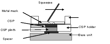
The Land of the package should be cleaning first by solder cleaner.
The package is put on the CSP plinth which is on the base unit with the spacer.
Then CSP is fixed by the CSP Holder.
Solder paste is added and printing it by a squeegee.
After printing, the printing mask unit is removed.
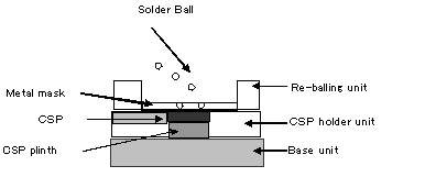
Remove the spacer
The re-balling mask unit is setting up instead of the printing mask unit.
The level of the CSP Plinth is down by the thickness of the spacer.
Solder ball is poured in, Then remove the re-balling mask unit
The CSP with solder ball can be removing with the CSP holder.
PLCR Re-Balling Jig (for lead pitch 0.5 ~ 0.8mm)
Re-Balling of fine lead pitch CSP is possible by PLCR re-balling Jig
The jig is consisted of the metal mask for re-balling, and printing.
The printing mask unit can be use for printing at re-balling,
and printing at soldering to the board.
The CSP after re-balling can be supply to the nozzle of the rework machine directly.
Outline
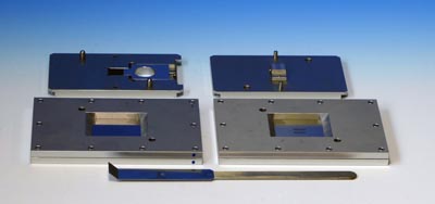
PLCR Jig is a manual re-balling jig for fine pitch CSP. PLCR re-balling jig can be fixed of the CSP, therefore, printing and re-balling for the fine lead pitch CSP is possible. PLCR Re-balling Jig is manufactured in accordance with the specification of the CSP. It is consisted as: |
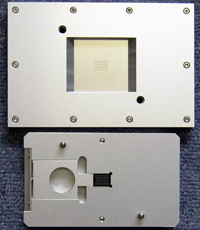 Re-balling mask Unit CSP Holder |
Re-Balling process-1: (Solder Printing)
|
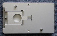 CSP Holder |
Re-Balling Process-2: ( Solder Ball added )
|
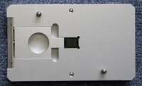 CSP Holded |
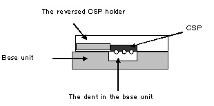
Re-Balling Process-3: (Solder ball heating )
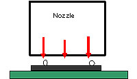
The completed solder ball on the CSP must be heating by the rework systme.on the board is set in the rework system and heating. It is for fixed of the ball to the package. In the case of the heating, the optimal temperature profile will be all-most same as soldering it, However, maximum temperature will be enough even if somewhat low. The optimal temperature should be decided by real operation.|
|
 |
After re-balling
The completed BGA should be solder printing again with the printing mask unit when replacing to the board. Then, the CSP is supplied to the nozzle of the rework system. It can be directly from the PLCP jig. However, SND-ADP parts supply unit will be more easy of supplying of the CSP.PLCP Printing Jig (for lead pitch 0.5 ~ 0.8mm)
| PLCP type Printing Jig is used when soldering CSP of fine pitch. They are both CSP which re-balling and or new one. The function is included of the PLCR re-balling Jig. However, when only the jig for printing is required, the PLCP type Jig for printing was prepared.
|
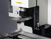 SND-ADP Parts Supply Unit  PLCP Printing Jig |
M.S.Engineering Co.,Ltd.
1-38-15, Okusawa, Setagaya-Ku, Tokyo, 158-0083 Japan. Phone: +81-3-4283-3951 Fax: +81-3-3728-5232
Copyright(C)2007 M.S.Engineering Co.,Ltd. All rights Reserved.
1-38-15, Okusawa, Setagaya-Ku, Tokyo, 158-0083 Japan. Phone: +81-3-4283-3951 Fax: +81-3-3728-5232
Copyright(C)2007 M.S.Engineering Co.,Ltd. All rights Reserved.
 PDF for Printing
